Peripheral Control     Robotics and Automation Made Easy

Step 2: Peripheral/Slot Assignment

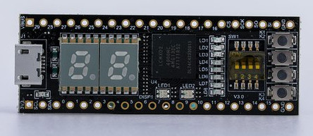
Slot / Pin Assignments
Open image in new tab and expand to see pin numbers.

Slot 0: Switches, LEDs, buttons, 7-segment displays
Slot 1: Pins 0, 1, 2, 4
Slot 2: Pins 5, 6, 7, 8
Slot 3: Pins 9, 10, 11, 12
Slot 4: Pins 13, 14, 15, 16
Slot 5: SI, SO, CSK, CS
Slot 6: Pins 16, 17, 18, 19
Slot 7: Pins 20, 21, 22, 23
Slot 8: Pins 24, 25, 26, 27
Slot 9: Pins 28, 29

Schematic: available here
Note that the pins labeled as I2C and SPI are also GPIO pins on the FPGA
Serial host interface on pins with label:
    SCL (output) : TX from FPGA to host
    SDA (input)  : RX from host to FPGA


Slot 0 is already assigned to the input/output devices on the FPGA board.
The API link points to the peripheral's README.txt file
The hardware link points to a schematic of any hardware required by the peripheral.
Please select a peripheral for each slot.

Motion Control 1 2 3 4 5 6 7 8 9
Dual DC motor controller
Dual quadrature decoder
Quad servo motor controller
Unipolar stepper motor controller
Bipolar stepper motor controller
Simple Input/Output 1 2 3 4 5 6 7 8 9
Quad binary output
Quad binary input
Quad bidirectional I/O
Quad Serial Output
User Interface 1 2 3 4 5 6 7 8 9
Quad WS2812 RBG(W) LED interface
Consumer IR receiver/transmitter
6/8 channel RC decoder
Audio square wave generator
Simple sound generator
80x40 color terminal on VGA
PS/2 mouse or keyboard input
Sensors 1 2 3 4 5 6 7 8 9
Quad Parallax PING))) interface
Quad event counter
Quad RC discharge timer
Octal RC discharge timer
7 channel line sensor
Instrumentation 1 2 3 4 5 6 7 8 9
Quad PWM output
Quad PWM input
2 MHz function generator