


Serial host interface on pins:
J2 pin 2 (output) : TX from FPGA to host
J2 pin 3 (input) : RX from host to FPGA
Note that the Runber does not support flash memory and the USB
interface is for download only. A complete system requires both a
Tx/Rx serial interface for host communication and a USB connection
for FPGA download.
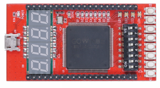
Slot / Pin Assignments
Slot 0: Switches, LEDs, buttons, 7-segment displays
Slot 1: J1 Pins 2 3 4 5
Slot 2: J1 Pins 6 7 8 9
Slot 3: J1 Pins 10 11 12 13
Slot 4: J1 Pins 14 15 16 17
Slot 5: J1 Pins 18 19, J2 pin 19 18
Slot 6: J2 Pins 17 16 15 14
Slot 7: J2 Pins 13 12 11 10
Slot 8: J2 Pins 9 8 7 6
Slot 9: J2 Pins 5 4 (only two pins in slot 9)
J2 is the top row of pins, J1 the bottom.
Slot 0 is already assigned to the input/output devices on the FPGA board.
The API link points to the peripheral's README.txt file
The hardware link points to a schematic of any hardware required by the peripheral.
Please select a peripheral for each slot.