Peripheral Control     Robotics and Automation Made Easy

Step 2: Peripheral/Slot Assignment

Users Guide and Schematic: available here.
Serial host interface on pins:
    Pin 112 (output) : TX from FPGA to host
    Pin 111 (input)  : RX from host to FPGA

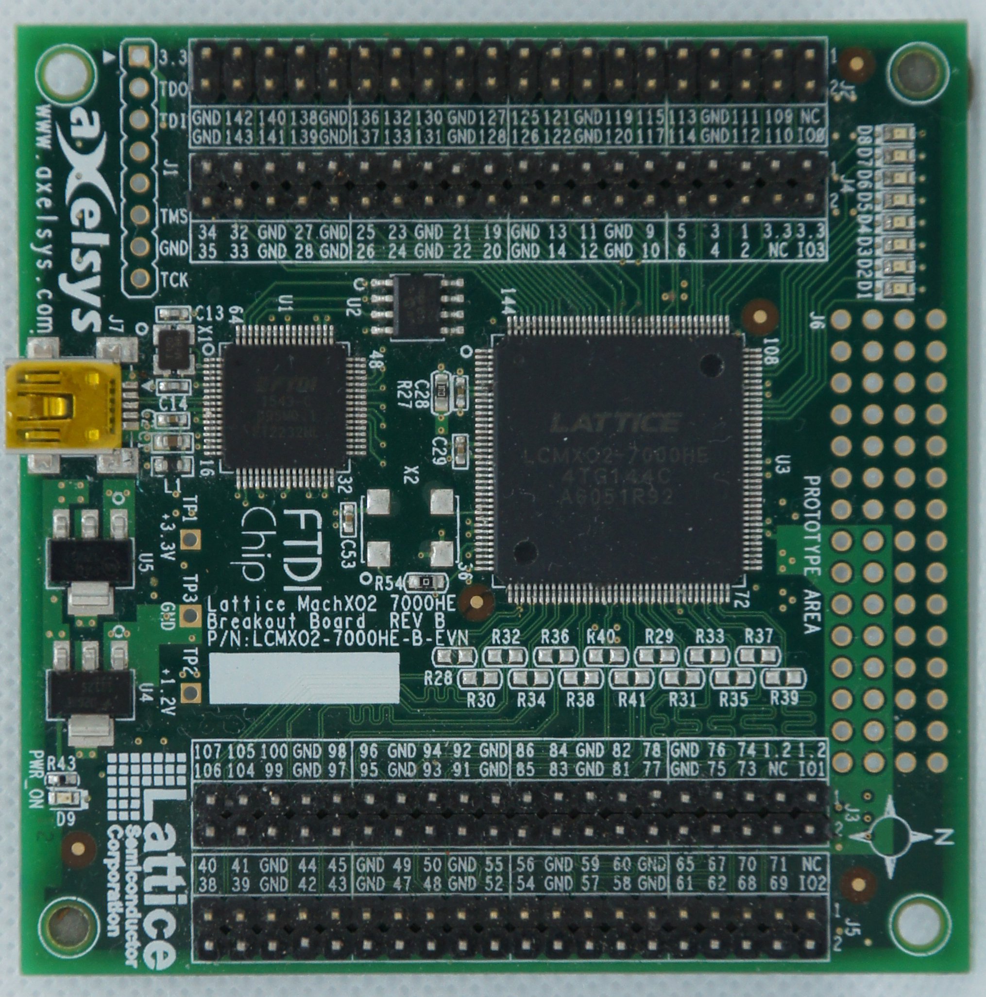
Slot / Pin Assignments
Open image in new tab and expand to see pin numbers.

Slot 1: Pins 143 142 141 140
Slot 2: Pins 139 138 133 132
Slot 3: Pins 128 127 122 121
Slot 4: Pins 117 115 114 113
Slot 5: Pins 35 34 33 32
Slot 6: Pins 26 25 24 23
Slot 7: Pins 22 21 20 19
Slot 8: Pins 14 13 12 11
Slot 9: Pins 10 9 6 5
Slot 10: Pins 4 3 2 1
Slot 11: Pins 47 48 49 50
Slot 12: Pins 52 54 55 56
Slot 13: Pins 57 58 59 60
Slot 14: Pins 61 62 65 67
Slot 15: Pins 94 93 92 91


Slot 0 is already assigned to the input/output devices on the FPGA board.
The API link points to the peripheral's README.txt file
The hardware link points to a schematic of any hardware required by the peripheral.
Please select a peripheral for each slot.

Motion Control 1 2 3 4 5 6 7 8 9 10 11 12 13 14 15
Dual DC motor controller
Dual quadrature decoder
Quad servo motor controller
Unipolar stepper motor controller
Bipolar stepper motor controller
Simple Input/Output 1 2 3 4 5 6 7 8 9 10 11 12 13 14 15
Quad binary output
Quad binary input
Quad bidirectional I/O
Quad Serial Output
User Interface 1 2 3 4 5 6 7 8 9 10 11 12 13 14 15
Quad WS2812 RBG(W) LED interface
Consumer IR receiver/transmitter
6/8 channel RC decoder
Audio square wave generator
Simple sound generator
80x40 color terminal on VGA
PS/2 mouse or keyboard input
Sensors 1 2 3 4 5 6 7 8 9 10 11 12 13 14 15
Quad Parallax PING))) interface
Quad event counter
Quad RC discharge timer
Octal RC discharge timer
7 channel line sensor
Instrumentation 1 2 3 4 5 6 7 8 9 10 11 12 13 14 15
Quad PWM output
Quad PWM input
2 MHz function generator