Peripheral Control     Robotics and Automation Made Easy

Step 2: Peripheral/Slot Assignment

Slot / Pin Assignments
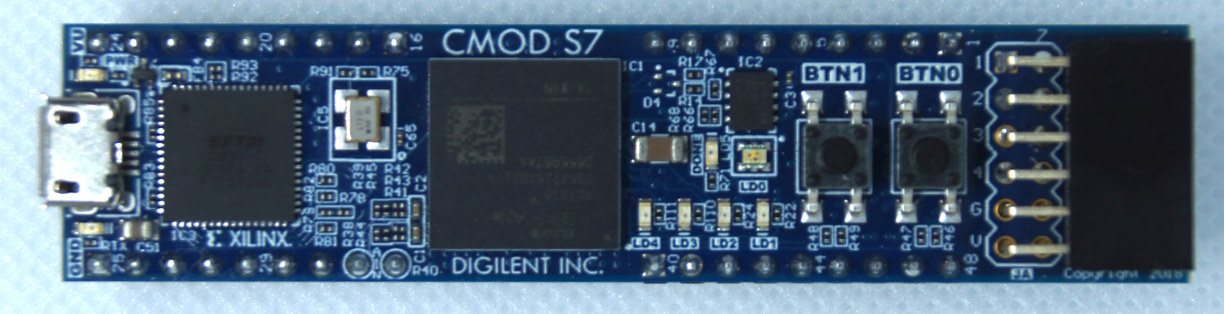
Pin numbers are for a 48 pin DIP package except for the top mounted Pmod connector.

Slot 0: Cmod S7 LEDs and buttons
Slot 1: Pins 4, 3, 2, 1
Slot 2: Pins 8, 7, 6, 5
Slot 3: Pins 19. 18.17.16
Slot 4: Pins 23, 22, 21, 20
Slot 5: Pins 31, 30, 29, 28
Slot 6: Pins 44, 43, 42, 41
Slot 7: Pins 48, 47, 46, 45
Slot 8: JA Pins 1, 2, 3, 4
Slot 9: JA Pins 5, 6, 7, 8
Slot 10: Pins 9, 40

Users Guide available here
Schematic available here


Slot 0 is already assigned to the input/output devices on the FPGA board.
The API link points to the peripheral's README.txt file
The hardware link points to a schematic of any hardware required by the peripheral.
Please select a peripheral for each slot.

Motion Control 1 2 3 4 5 6 7 8 9 10
Dual DC motor controller
Dual quadrature decoder
Quad servo motor controller
Unipolar stepper motor controller
Bipolar stepper motor controller
Simple Input/Output 1 2 3 4 5 6 7 8 9 10
Quad binary output
Quad binary input
Quad bidirectional I/O
Quad Serial Output
User Interface 1 2 3 4 5 6 7 8 9 10
Quad WS2812 RBG(W) LED interface
Consumer IR receiver/transmitter
6/8 channel RC decoder
Audio square wave generator
Simple sound generator
80x40 color terminal on VGA
PS/2 mouse or keyboard input
Sensors 1 2 3 4 5 6 7 8 9 10
Quad Parallax PING))) interface
Quad event counter
Quad RC discharge timer
Octal RC discharge timer
7 channel line sensor
Instrumentation 1 2 3 4 5 6 7 8 9 10
Quad PWM output
Quad PWM input
2 MHz function generator